How Circuits Work

We use electric circuits everyday in daily lives without even relising it. When you wake up in the morning and turn your light on, you just used a circuit. When you start your car to go to work, you just used a circuit.

There are two types of circuits, series and parallel. Parallel circuits have two or more paths for current to flow through whereas a series circuit only has one path for the current to flow through. There are advantages and disadvantages to using series and parallel circuits. A disadvantage of using a series circuit is that if one bolb breaks or the pathway is broken in anyway, then all the other bulbs will go out. Some advantages to using a series circuit are, you can add more power sources, like batteries, and increase the force of the output whcih supplies you with more power. Some advantages of parallel circuits are, they have consistent voltage, they have independant components, meaning when you turn one on, you don’t turn everything else on.

You can find series circuits in factories as they are more practical to have than parallel circuits. Parallel circuits can be found in your house when turn on your light. You can also find series circuits on your christmas tree lights and string lights.

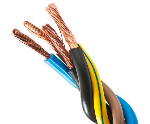
An electric circuit is like a path made of wires that electrons can flow through. A battery or other power source provides the voltage that makes the electrons move. When the electrons reach a component like a light bulb, they give it power to make it work.

Evaluation

I think the construction for my house model went well. We worked on it and got it done quite fast. We were able to build the walls, roof, floor and details in one period. Some difficulties I came across whilst creating my model were, the circuit and installing it. The circuit took a while as I had to do a lot of research on it and it took me a while to actually complete it. I found it difficult to install the circuits as it was hard to cut holes into the roof to put the LED light in. It was also hard because when we did get the LED into the hole, the wires would touch, therefore breaking the circuit. Some changes we made to our model was instead of making our house have 5 rooms we changed it to 4 so that we would be able to make the walls look nicer and also becuase f our time constraints. We also chenged our plan for having one series circuit to light up the whole house. Instead we made four parallel circuits. We did this because we didn’t have space to stick one big circuit on our house.

…And Some More Work On The House

This lesson I put in the lights to the second storey. It was a much quicker process as the walls were thinner on the second storey. I cut little holes so we could attach the LED’s and switches to the wall. Once we had done that I tested the switch to make sure our LED was still working and to make sure no wires were touching. Fortunately they weren’t which speeded up the process further. Once I ahd checked I taped the switch, wires and LED up so they couldn’t fall out or move around. As there was no roof to rest the battery on, I had to tape it to the back of the house along with the wires. I only just managed to install the two sets of lights before the bell went.

Further Work On The House

This lesson I installed the top floors lights with the help of Laura. We had to cut little holes into the roof for the switch and LED’s to sit. Once the LED’s and switches were secure we had to test them to see if they still worked. Occansionally the LED wouldn’t work so I had to take it out and make sure none of the wires were touching eachother. Once we checked the lights were working we taped the battery to the roof and did the same with the wires and LED. We had some trouble taping the switch because every time you pushed it, it would push through it’s hole in the wall. We fixed this problem by taping a support below it on the back of the house.

The Construction Of The House

This lesson Laura and I began constructing our house. We chose our box and cut it down with a box cutter. Whilst Laura constructed the inner walls I finished off my final circuit and made measurments for the roof of the house. Once I had worked out the measurements for the house I had to find some cardboard to apply them to. I then glued the roof onto the house and made some little paintings to decorate the ineterior of the house. I also helped Laura construct the door to the house. I tested out each circuit to check none of the LED’s had blown and were ready to install next lesson.

Constructing My Circuit

This lesson I put together my circuit based on the discoveries I made lesson. First I had to get the clear LED’s I wanted to use, I then collected my 9v batteries, I found some switches, I cut myself some wires and then gathered the resitor I selected last lesson. I connected my resistor to the red wire and then connected the longer wire of LED to the other wire of the resistor, I then attached another wire to the other side of the LED. I attached that wire to my button and then attached another wire to the other side of the button. I then attached the other end of the wire to the end of the black wire. I know it sounds confusing (and it is) but it makes more sense when you see the actual circuit.

It took some time as the wires were reasonably fiddly and hard to curl around other wires but I got there in the end and ended up making 2 more with a total of 3 circuits completed.

OHM’s Law

This lesson I worked out where I was going wrong with my previous circuits. I wasn’t calculating my voltage. I hadn’t realised that with 4 LED’s all needing about 1.4 volts to light and a 9V battery that they might blow or need a resistor. I did some research on OHM’s law and found out OHM’s law is a way of describing the relationship between the voltage, resistance and current using maths. The formula for this law is:

V=RI

  • V is the symbol for voltage
  • I is the symbol for current
  • R is the symbol for resistance

By the end of the lesson I worked out what resistor I needed:

My Resistor

Putting It Together

This lesson I examined what other people were using to create their circuits. I had a few ideas on how I was going to do mine based on what others had done; unfortunately we were out of cradles and switches. Instead I experimented by taping batteries together and trying to use buttons. I had no luck. I finally constructed a circuit by the end of the lesson using a 9v battery, a resistor, wires, a switch and 4 LEDS. I tried to switch on my circuit but it didn’t work unfortunately.

I also don’t have any photos for this lesson as my phone was dead.

The Circuit

This lesson I spent my time experimenting with circuit components. We got to play around with LED’s, resistors, wires, motors and other components. I learnt how to strip a wire and to test if a battery still works. By the end of the lesson I learnt how to make a motor run and had a basic idea of how to construct an electric circuit that would light an LED. I collected some components I would use in the next lesson; switches, buttons, wires and an array of batteries.

The Design Process

This lesson I decided what I was going to make for my project and how I was going to do it. My partner and I decided to make a house. We spent the lesson working on what materials we would need and where we would source them from. We discussed that the house would be 2 stories high and would have 4 rooms, a bedroom, bathroom, kitchen and living room.

Materials:

  • 4 9v batteries
  • 8 wires
  • 4 button on wires
  • 4 resistors
  • 4 clear LED lights
  • Cotton balls for pillows
  • Cardboard for house
  • Couch
  • Bath
  • Fabric for flooring
  • Fake plants